
Five Years of Testing using the Semi-Automated Ultrasonic Time of Flight Diffraction System
S. A. WEBBER,(Snr. Technical Officer) SIGMA PROCESS SOLUTIONS,
Australia.
| Five Years of Testing using the Semi-Automated Ultrasonic Time of Flight Diffraction SystemS. A. WEBBER,(Snr. Technical Officer) SIGMA PROCESS SOLUTIONS, Australia. |
This paper provides a brief description of the Time of Flight Diffraction (TOFD) test system and also describes a couple of case histories where the system has been successfully applied. The T.O.F.D. system has been contrasted with the conventional manual ultrasonic technique. Whilst the T.O.F.D. system has proven potential, and is without doubt a valuable tool that will continue to gain market share in the inspection industry, conventional manual ultrasonics still has its part to play and will survive for some time to come. One of the outstanding issues facing the T.O.F.D. systems is the question of acceptance testing which is still the predominant convention specified in most standards. Training for a T.O.F.D. system technician is particularly important and the author suggests there are more traps for the unwary than with the conventional manual ultrasonic systems. The overall judgement of the T.O.F.D. system is that it is a most welcome and powerful tool in the hands of the right operator and will do much to boost the prominence of Non-Destructive Testing.
Keywords: TOFD. ULTRASONIC. RINGS. LONGITUDINAL. WELD.
Currently, one of the most common ultrasonic methods being applied in the field of weld and other product testing is that referred to as conventional manual ultrasonics. The manual system has been employed successfully for many years in basically the same form utilising hand held probes and producing rectified A-scans from the returned ultrasound. The rectified A-scans are then viewed dynamically by the test technician who interprets various components of the displayed A-scan ie shape, time displacement, amplitude etc. in order to develop a mental picture of what is giving rise to the returned signals. Considerable skill, and often specific knowledge of the item under inspection, may be required for successful interpretation of the A-scans as not all returned signals may result from the presence of defects. One of the drawbacks associated with conventional manual ultrasonics had been its inability to produce meaningful hard copy test results and in a form which allows third party, or post test evaluation of confirmed or suspect defect areas. Another drawback of conventional manual ultrasonics, especially in the case of having to monitor a defect over a number of years, has been the lack of reproducability in defect evaluation, as the system relies so heavily on the interpretive skills, memory and availability of the test technician. Even with the introduction of many of the modern digital conventional A-scan machines that allow all test parameters to be stored, including often the ability to store A-scans, the same problem persists. It is generally acknowledged that the manual ultrasonic testing technique is highly subjective and the industry would always view favourably any alternative system that proved to be less subjective in nature. One such alternative system, becoming better known in commercial circles by non-destructive testing practitioners and users of non-destructive testing services, is one which employs the Ultrasonic Time of Flight Diffraction Technique (T.O.F.D.). Dr Maurice Silk pioneered the T.O.F.D. technique 27 years ago at the National Non Destructive Testing Centre at the United Kingdom Energy Atomic Energy Authority, as a need had arisen to reliably detect, size and monitor known defects in one of the United Kingdoms nuclear power plants. The technique proved successful for several years after which it was further developed to that which we see to-day commercially available from a small number of vendors.
The T.O.F.D. systems provide for fully or semi-automated inspections and production of pictorial images rather than the raw A-scan images seen on conventional ultrasonic machines.
The TOFD system relies not only on specularly reflected ultrasonic waves but also on the diffracted waves which occur as a result of wave interaction with any defect which may occur within its path. The A-scan waveforms, through software manipulation, are converted into a pictorial image, referred to as the T.O.F.D. scan image. Figure 1 describes how the T.O.F.D. images are produced and reveals an actual T.O.F.D. scan showing a defect within the body of a weld. Unlike conventional ultrasonics the TOFD system does not totally rely on amplitude in the assessment of defect size by typically the 6 or 20dB drop methods. Evaluation of defects with the T.O.F.D. system occurs after the image of the defect is acquired and displayed on screen. The defect position and size are determined by placing software generated, calibrated, cursers on the image of the defect displayed in the on screen T.O.F.D. image. Other characteristics of the image are scrutinised to identify the nature of the defect and standards, typically the British Standard 7706 " Calibration and setting-up of the ultrasonic time of flight diffraction technique for the detection, location and sizing of flaws" have been developed to aid in the interpretation of T.O.F.D. images. There are also other international standards published that provide guidance for setting up and performing inspections with the T.O.F.D. system. The system relies on the use of two ultrasonic probes in a pitch and catch arrangement producing a refracted longitudinal wave at angles similar to those used in conventional A-scan systems eg 45-60-70 degrees. In addition, a further wave is generated which is transmitted along the tested items surface directly between the transmitting and receiving probes, referred to as a lateral wave with the same velocity as the refracted longitudinal wave. The effect of, and image produced by the lateral wave, can be seen in figure 1 and is the horizontal line at the top of the T.O.F.D. scan image. In a defect free item the next wave to appear would be the refracted normal wave returning from the back wall and this is seen in figure 1 on the bottom of the T.O.F.D. scan image. In the event of defects being present then the reflected and diffracted waves return at a time between the upper, lateral wave, and the lower back wall wave, refer figure 1.
 |
There are two main types of T.O.F.D. scan images and they are referred to as D-scans and B-scans. These names are given simply to distinguish the relationship between the scan and beam directions, refer figure 2. The D-scan may be the most widely performed scan typically with the ultrasonic probes straddling the cap of a weld then running down the weld length. If defects are found then a transverse scan (B-scan) may be performed to gather greater detail of the defect and its position relative to the weld centre line and true distance below the surface.
 Fig 2: to the left describes the relationship between probe movement and beam direction for D-scans and B-scans. Fig 2: to the left describes the relationship between probe movement and beam direction for D-scans and B-scans. |
The former Queensland Electricity Commission took delivery, in January 1995, of the AEA Sonomatic T.O.F.D. system primarily for the inspection of all their generator retaining rings. Retaining rings are plant items, refer to figure 3, that form part of high-speed rotating generator rotors and are known to have failed catastrophically in other parts of the world. Older retaining rings are manufactured from 18Mn-5Cr material and are known to suffer from stress corrosion cracking under certain conditions ie. high levels of moisture and applied stress. They require regular inspection as the items are always under stress both whilst rotating in service at speeds of around 3000rpm and also when stood down as they are a shrunk on item. Retaining rings form part of a power stations main generator rotor and the majority of them operate in a controlled environment during service ie dry hydrogen atmosphere with dew point controls. The rings are at risk if their environment is not monitored and controlled properly, and also when they are removed from service during maintenance outages. Whenever rotors are removed from their stator they are put in to a clean conditions area, often enclosed in a tent with dehumidifiers for protection. A great deal of emotion and controversy surrounds the argument for replacement of 18Mn-5Cr retaining rings with those of 18Mn-18Cr composition. The newer 18Mn-18Cr material is reported to be impervious to stress corrosion cracking although stories of in service defects in this material are starting to emerge and the author makes no judgmental comment at this stage. Refer to figure 5 which shows four typical T.O.F.D. scans of defects in generator end rings, 2 off in 18Mn-18Cr material and 2 off in 18Mn-5Cr material. Most of the original equipment suppliers are actively seeking to convince utilities to change to an 18Mn-18Cr material and the costs of doing so are considerable with consideration also having to be made of the risk of damage to the underlying windings and insulation in the replacement process. Cost justification may be warranted in the event of having to replace an 18Mn-5Cr as a result of it being found defective, however the author would challenge the argument for replacement as a matter of course. Providing retaining rings are properly maintained they will perform trouble free for the life of the plant, and in power stations belonging to the former Queensland Electricity Commission many 18Mn-5Cr retaining rings continue in trouble free service and are in excellent condition. Prior to the introduction of the T.O.F.D. systems one of the compelling reasons for considering retaining ring upgrading would have been the lack of confidence in regular manual ultrasonic test results. Older retaining rings of 18Mn-5Cr composition are renowned as being extremely difficult to test, in spite of their often plain geometry. Defect indications could easily be masked by noise resulting from scatter of the ultrasonic beam from the coarse grain structures found in these austenitic materials. The former Queensland Electricity Commission gained a great deal of experience in testing these items using conventional manual ultrasonic techniques, usually at every power station unit overhaul. It was common, when using manual ultrasonic testing to find a number of indications on the rings inner surfaces and at locations where cracking was theoretically predicted ie shrink on fit areas. It should be noted that the normal strategy for testing these items when they have been removed from the stator shaft would be to apply dye penetrant on their inner surfaces. Reliance on dye penetrant alone however is controversial, and not without good reason in the experience of the author having been witness to the failure of dye penetrant inspection to reveal very significant cracking in retaining rings. Removal of the retaining ring from the rotor, to further investigate the source of ultrasonic indications, is both expensive and has potential of causing damage in the removal and replacement process. For these reasons, and naturally the reputation of the test technician, making a judgement call on these items is not for the feint hearted as the truth will out during post removal inspection. Often in the case of excavation of defects reported in welds the reported defect may not actually be verified as the excavation process ie grinding or flame gouge, may obliterate the area where the defect has been reported.
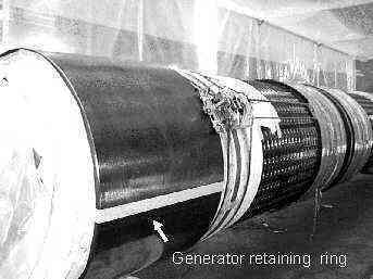 Fig 3: The figure to the left is a typical generator retaining ring, removed from the stator and undergoing automated T.O.F.D. inspection. Note the rotor is enclosed in a clean condition area. Fig 3: The figure to the left is a typical generator retaining ring, removed from the stator and undergoing automated T.O.F.D. inspection. Note the rotor is enclosed in a clean condition area. |
After inspection of only the second set of generator retaining rings tested with the newly acquired T.O.F.D. system the author was obliged to report the discovery of a defect in the order of 12mm in height on the inner surface of one of the retaining rings refer figure 4. The retaining ring had previously been ultrasonically inspected over a period of 25 years using the manual method with no defects being recorded which raised the possibility of a defect occurring between inspection periods. The finding was however perplexing, as there was no record of any significant operational changes in the service history of the plant item which may account for the defects initiation and growth. For the items in question crack growth rates are theoretically predicted as being very high, given the right conditions ie moisture and stress. The particular retaining ring was removed from the rotor shaft and fluorescent dye penetrant was applied to the area of concern on the inside surface of the ring. The penetrant test failed to show any indication in the area of concern. Another T.O.F.D. examination was performed on the outside surface of the ring and the defect was revealed to be exactly as found during the initial inspection. A decision was made to allow some minor excavation, which after finite element analysis by the OEM suggested may be to a depth of 6mm. Excavation was initiated with the use of a light grinder and after removal of approximately 250 micron a crack like indication was revealed. The defect being no more than 250 micron below the inner surface naturally escaped detection by the dye penetrant process . Metallurgical investigation revealed the defect to be slag entrapment resulting from the time of original manufacture. The defect, being verified as an original manufacturing defect, had to have been present and overlooked during all past manual ultrasonic inspections. This was convincing evidence of the inappropriateness of the manual ultrasonic test technique to adequately inspect these plant items. It should be realised that in the earlier days of retaining ring inspections the conventional manual technique was the only tool available for in situ testing of these items. The defect was finally excavated to a depth of 6mm and carefully blended after which a filler material was applied prior to the ring being refitted to the rotor and returned to service. This action was taken to enable the manufacture of a replacement ring for fitting at a later planned outage. The decision to return an 18Mn-5Cr retaining ring to service with such an excavation may raise eyebrows in some quarters but as previously stated calculations had predicted, and probably conservatively, that this was totally acceptable. Such a decision would not surprise the author as he has seen, and is still in possession of, 18Mn-5Cr. retaining rings which have major cracking in their highest stress areas and which have survived without failing in service. This is not to advocate a lack of caution when dealing with these items but simply an observation that perhaps these items are tougher than we may be led to believe by some.
 Fig 4: The figure to the right is displaying a T.O.F.D. image of a crack on the inner surface of a generator retaining ring. Fig 4: The figure to the right is displaying a T.O.F.D. image of a crack on the inner surface of a generator retaining ring. |
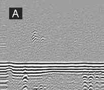 | 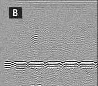 |
| The figures A & B to the left show defects at about 12mm below the inner surface in 18Mn-18Cr retaining rings. | |
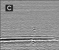 | 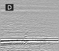 |
| The figures C & D to the left show defects on the inside surface of 18Mn-5Cr retaining rings. | |
| Fig 5: The figures A & B to the left show defects at about 12mm below the inner surface in 18Mn-18Cr retaining rings.The figures C & D to the left show defects on the inside surface of 18Mn-5Cr retaining rings. | |
The power of the T.O.F.D. technique as a tool in the inspection of generator end rings had been convincingly demonstrated and remains the test of choice for these plant items and is recommended as such by the American Power Institute EPRI after extensive research into examination of generator retaining rings.
Some years ago the former Electricity Commission embarked on an extensive program of testing certain pipe systems in a number of their more modern power stations. The program was centred around the inspection of a number of critical welds in longitudinally seam welded pipe. The program was initiated as a result of catastrophic failures having occurred in welds of similar configuration in the United States of America. These failures in the United States highlighted a fundamental problem associated with this type of joint, that being their inherent weakness. These joints are constantly under full hoop stress whilst in service and all things being equal will suffer from creep damage before any of the circumferential welds on the same fabrication. Any defect within these welds would further reduce their strength in what is already a fundamentally weak joint and probably act as a crack initiator, accelerating weld failure. Whilst all the seam welds in the Queensland power stations had undergone 100% testing at their overseas place of manufacture, concern existed over the effectiveness of these tests. The weld joints ranged in thickness between 33mm and 70mm and were originally factory inspected by the radiographic method using a linac and the double wall single image technique. A specified film density of two was achieved by placing two radiographs, one on top of the other, and it was considered improbable that the technique would reveal the type of defect likely to occur. The most likely defect was considered to be lack of inter, or side wall, fusion. The welding process was an automated one and involved submerged arc for the root region then fill and cap achieved using a narrow gap metal inert gas process. Whilst manual ultrasonic testing was envisaged for the site testing program, concern existed over the ability of the technique to effectively size any side wall or vertically aligned lack of fusion. The concern arose as narrow (J) weld preparations were used throughout fabrication of these items resulting in almost vertical side wall profiles, and therefore any lack of side wall fusion was likely to be aligned almost vertically. The former Electricity Commission had constructed a test block simulating lack of side wall fusion in the (J) prep configuration and demonstrated, through round robin tests, that whilst its detection was probably achievable the actual through depth sizing was extremely difficult. The ability to perform accurate defect sizing, using ultrasonics, is very dependant on the degree of ultrasound reflection from the particular defect. If the vertically inclined face of the defect was linear and smooth, as would occur on an unfused weld preparation, then any ultrasonic reflection would be almost totally specular and defect detection improbable. By contrast, if the vertical profile has some degree of roughness then some scatter of the beam back to the receiving ultrasonic element could be expected. Another compounding problem in testing longitudinal welds is their scanning surfaces are curved and not flat as occurs with conventional butt weld testing. With these curved surfaces particular care has to be applied in adjusting stand off distances when determining defect position and through height. The curved surface can also cause a focusing effect as the inspection probe develops a concave face, which in turn can effectively produce higher sensitivity and may cause problems if a dB dependant recording criteria is being applied. The focus affect may also invalidate any beam profile used for accurately sizing defects, typically by the 6 or 20dB methods, if they have been constructed as they are traditionally on a flat surface. For the purpose of the inspection program it was considered that any lack of fusion defects would be a mixed bag ranging from totally specular reflectors to those which provided sufficient reflection to allow more accurate sizing.
 Fig 6: The above T.O.F.D. scan image reveals the defect not to be root connected and consisting of two separate defects. Fig 6: The above T.O.F.D. scan image reveals the defect not to be root connected and consisting of two separate defects. |
The first site survey in the inspection program was conducted by an overseas contractor who was considered as being one of the experts in testing longitudinal welds using manual ultrasonic techniques. It was decided that the Commission would apply their T.O.F.D. system, which until that point had only been used for generator end ring inspections, on any defects reported by the contractor. It was not intended that the T.O.F.D. was to be used in an audit role but simply used to gather confidence in its ability to test welds and provide some specific training in this area. In the very early stages of the first site survey, utilising the manual ultrasonic technique, a defect was reported in a 33mm thick pipe section, which was considered significant enough to warrant a repair. The defect was reported to be root connected, 13mm in the through height dimension and 40mm in length. Based on the reported defect dimensions the contractor recommended that a repair should be made. The repair could not be accommodated within the scheduled shut down period of the plant and the suggested strategy was to schedule the repair some six months later. The cost of any shut down of a large generator unit is very costly and a second opinion was immediately sought suggesting the application of the T.O.F.D. system to interrogate the defect area in question. The T.O.F.D. system was applied and the defect was imaged very successfully and is shown in figure 6. As may be seen in the figure the T.O.F.D. image revealed the defect not to be root connected and consisting of two individual defects each 10.5mm long and separated by 21mm. As a consequence of being able to view and calculate the defect more accurately, courtesy of the T.O.F.D. equipment, calculations determined that the formerly recommended repair was not necessary and the item was returned to service with the added recommendation that it be monitored over time using the T.O.F.D. system and at intervals coincident with normal outages. The same defect has undergone T.O.F.D. examination subsequently some three years later and confirmed not to have grown. Clearly there was a large discrepancy in the test results between the manual and T.O.F.D. ultrasonic inspections and this had to be considered before determining the future strategy applied to the balance of longitudinally welded joints in that particular and other remaining power stations. The strategy developed, and currently applied and providing a high level of confidence is the combination of manual and T.O.F.D. techniques. The manual technique system is used as a first pass and the T.O.F.D. system is applied to areas where defects that exceed a pre determined criteria are encountered. An important prerequisite of the manual inspection is careful calibration on a calibration block that has a curved surface and a number of side drilled holes. This calibration serves as an aid in beam profile construction and importantly establishes the defect recording criteria. It has been mooted that the manual pre testing may be foregone and all welds simply tested using the T.O.F.D. system alone. In the authors experience the manual inspection is superior in these cases as it achieves a greater coverage on either side of the weld as those who are familiar with manual inspection of welds will recognise, the scanning pattern involves a raster pattern with the probe moving toward and away from the weld toe. Most T.O.F.D. scanning patterns, as described earlier, tend to be "D" or "B" scans, the one achieving the fastest coverage being the "D" scan. In order to achieve the equivalent coverage as the traditional manual ultrasonic technique the "D" scan would have to be done a number of times to ensure the weld volume and adjacent parent plate are adequately inspected. It can be argued that this can be overcome by performing a number of "D" scans with the probes focused at different depths. Another alternative would be to perform multiple head "D" scans but these require the appropriate software and capability to monitor loss of coupling for all probes. If the T.O.F.D. system is applied utilising a single "D" scan with two probes, defects may escape detection, the extent to which depends on a number of factors similar to those affecting coverage using conventional manual ultrasonics ie probe frequency, size, axial focal point etc. The author can attest to the validity of these comments after having acquired considerable experience in revisiting areas where manual ultrasonics has located fine sidewall defects and reinspecting them using single T.O.F.D. "D" scans with one pair of probes. Once the manual ultrasonic operators are coached, utilising the T.O.F.D. system to provide initial feed back through scans on reported areas, a very powerful test regime is established giving a high level of confidence in the test results. Another very important deciding factor which led to the combination of T.O.F.D. and manual techniques was the need to filter the number of reflectors to those which were significant and this normally dictates the use of a go, no go, procedure involving DAC curves and an agreed recording level. This is of course the recognised system used in many parts of the world and works well. Acceptance level amplitudes are important not only for dictating levels of test sensitivity but also for establishing the economics of the test. If an amplitude acceptance level was not set and the test technician instructed to size all indications, whilst using very high gain settings, the test regime would be impractical and cost prohibitive in most cases. It is often stated that, for the T.O.F.D. technique, amplitude is not too important as defects are simply measured on the captured scan image by measuring their visible extremities. Whilst this is true, having to analyse some T.O.F.D. scan images to codes which specify defect dimension limitations can be time consuming and at times a nightmare as often normal quality welds can contain a myriad of defect images when scanned at high levels of sensitivity. It was also with these considerations in mind that the decision was made to apply the strategy of combining both manual and T.O.F.D. techniques to the longitudinal weld surveys. In comparing costs and after considering the set up times, capital outlay for a T.O.F.D. system, speed of scanning and full interpretation of the T.O.F.D. images, manual ultrasonics begins to compare quite favourably. For those who have reservations on the acceptance level form of testing, using amplitude to decide on whether or not to record a defect, the fact should be considered that weld failures in pipes as a consequence of poor weld quality are quite few and far between.
Whilst these modern Time of Flight Diffraction systems offer great advantages they are also considerably more expensive than conventional ultrasonic machines. Before the higher cost of purchase, or hire, of the Time of Flight Diffraction system can be justified the end user has naturally to consider the cost benefit. It was mentioned earlier in this paper that a particular inspection resulted in avoiding the cost of a power station unit shutdown and it could be argued that this single inspection more than returned the capital outlay expended on the T.O.F.D. equipment. However, and lest we forget, we live in the world of funny money and the following has to be considered. As both the power station owner and T.O.F.D. owner, in the case of the inspection being spoken of, were one and the same. then clearly the T.O.F.D. equipment paid for itself in that one test alone. It can be considered also that the T.O.F.D. equipment in this situation is both cost effective and a worthy value adding piece of equipment. Ironically the argument can be considerably different if for the same test situation the owner of the plant undergoing inspection and the owner of the T.O.F.D. equipment were not the same eg the power station was government or privately owned and the T.O.F.D. equipment was provided by a commercial inspection company. For this scenario the test took no more than one day and the inspection company therefore would only be entitled to charge the power station owner for one day of services. It can be seen that for these situations the cost justification of any T.O.F.D. system could be difficult, as recuperation of the capital outlay may not be realised within an acceptable period.
In the opinion of the author the T.O.F.D. system is a must for the accurate sizing, positioning and characterising of weld and other defects. This is especially the case where high risk or cost is involved and those situations where defects are to be monitored over time. An example of the reproducibility capabilities of the T.O.F.D. system is illustrated in figure 7 where two images of T.O.F.D. test scan results are shown resulting from inspections that were four years apart. It may be observed that whilst the latest T.O.F.D. scan image, which is the upper of the two scans , was acquired at a higher sensitivity there is excellent correlation in the defect images.
 |
The T.O.F.D. technique is also the ideal tool for managing inspection programs for 18Mn-5Cr generator retaining rings. It should be emphasised that, for testing these items in particular, the test technician must have a very thorough knowledge of the issues associated with generator retaining rings and have proven experience in their inspection.
A very important issue that should be resolved, and potential users of T.O.F.D. services should be wary of, is that of media compatibility between the various T.O.F.D. systems that operate in the market. A customer may engage a supplier of T.O.F.D. services and find he has been compromised into having to use that same company at a later date as only that supplier can read any electronically stored data of test results. This becomes a real issue when the customer requests that the T.O.F.D. data, from which the T.O.F.D. image and test parameters are produced, is to be held by themselves. The customer may wish to retain the test data for quality assurance purposes, ie retention of test results, but the other important use of the electronic data is to enable its recall into another T.O.F.D. system to provide identical test set up parameters as those used in the initial test. If the T.O.F.D. service provider produces electronic data that can only be read on their system then the customer may lose the ability to go to competitive tender for future work. The customer should be wary if the testing company makes the claim that they, and not the customer, are obliged to retain the test data citing some in house quality assurance or other reasons. Even if the testing company has National Association of Testing Authorities (NATA) accreditation, which will have as part of its registration requirements guidelines for the storage and retention period of test data, the customer has the right to store the data themselves. It should be noted that if the customer intends to call for electronic data he must specify so on the contract of service along with the format of the storage media required. T.O.F.D. scans with set up data captured in electronic form can be massive and the customer will naturally bear the cost which may involve burning onto and presenting in CD or other bulk storage format rather than floppy disk.